If you follow my Facebook page, you might have noticed I announced a technical project. Well, here it is! I'm gonna make a small LED spot light. Last Halloween, we had a big lack of proper light. We wanted to use candles and lanterns, but the flames kept going out. So no more candles this time! And since I like to tinker with electronics, I wanted to make something myself.
The light will be a green LED spot light, powered by 24 high powered green LED's. Of course, you can use other colors, I'll explain later on how to do that. But first, we're gonna make a circuit board, and that's what this post will be all about. The simplest option when building a circuit is using prototyping board. This is a circuit board with copper strips and holes already in place. You have to use wires to build the proper connections. Cheap and easy, but also messy, and in this case, the placement of the components was pretty important, so I had no other choice than to make a real circuit board.
The circuit layout
First of all, you need to draw the circuit board layout. There's plenty of software that does a good job of converting schematics to circuit boards. However, these tools come with a learning curve, and I'm lazy. Besides, it's a very simple circuit, so it wasn't really difficult to draw it by hand. The only requirement was that the entire board was about 9 cm in diameter (it will be disc shaped), and the LED's should be in a nice pattern.
I used LibreOffice Draw for creating the layout. Since a few weeks, I ditched Windows and switched to Ubuntu. Works really great, transition to a new OS went very smoothly. LibreOffice is included with Ubuntu, and it's a very powerful office suite. Here's what the layout looks like:

Printing and etching
The method I used for etching the board is the so-called toner transfer method. The traditional method has always been using a photo sensitive laquer and UV light, but this requires a UV exposure unit. Since I'm not only lazy but also cheap, this wasn't an option. The toner transfer method is very popular among hobbyists. I'm not gonna explain in too much detail how it works, google it if you want a complete tutorial. What it comes down to: you print the layout on a laser printer and then put it on the board and heat it so the toner melts and sticks to the board.
I don't have a laser printer at home (I'm cheap, remember?), but I do have access to one at work. I printed a few copies and gave it a try. After applying the toner to the board using an iron, you're supposed to soak the paper in water until it becomes soft enough to remove it without damaging the circuit layout.
First, I tried using regular white A4 paper. Didn't work! It was almost impossible to remove after ironing. After googling what kind of paper I should use (wich I should have done first to begin with...) I found out glossy magazine paper is the best. One thing you should keep in mind is that you have to mirror the layout before printing, or it won't be right! I forgot it this time, but luckily that wasn't a problem for this one.

You probably won't be able to transfer the toner flawlessly. There will always be small pieces that either don't get hot enough or don't get enough pressure. No problem, this is easily fixed. Most permanent markers' ink is resistant to etching. I used a Staedtler Lumocolor black marker to correct any flaws.

Next step: etching! For this, I used ferric chloride. If you're interested in the chemistry behind it, here's how it works:
2FeCl3 + Cu -> 2FeCl2 + CuCl2
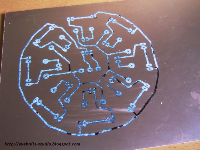
Be careful with this stuff! It's toxic and corrosive, so wear gloves and safety goggles. The ferric chloride solution should be warm, so I placed the container in warm water. If it's too cold, it takes too long to etch a circuit board. I submerged the board in the etching solution and slowly stirred it, so the dissolved copper washes away. I didn't take pictures of the etching process, because I was wearing gloves and didn't want to handle my camera while working with dangerous chemicals, but here's the result:

Voila! After etching, the board should be thoroughly cleaned and dried. The remaining bits of copper near the layout are for testing the etch-resistance of several other markers. One final step is required before the circuit can be assembled.
Drilling and cutting
Unless you're making a surface mount circuit board, you'll need to drill holes for the components. The holes are tiny (less than a millimeter for standard components), so a standard drill won't work. The recommended tool is a Dremel and a vertical drill stand.
There are two types of drills for circuit boards: HSS (high strength steel) and carbide. HSS drills wear out faster, especially if the board contains fibreglass. Carbide drills last longer but are quite brittle. If you use these, you definitely need a drill stand!
Drilling the holes makes a bit of a mess, so I did it in my basement. Not too much to say about it, it went fine without any problems. After drilling, I removed the remaining toner with acetone cut the board into a circular shape using my Dremel and grinding wheels, and made three small indentations in the outline. Why I did that will become clear in the next post!


0 reacties:
Een reactie posten